The following article was the front page cover story in
T&D World’s January 2022 Edition.
Every day, Atlantic City Electric Co. performs work as part of a strategic effort to modernize and strengthen the local energy grid. This effort includes dozens of targeted projects to install stronger utility poles and state-of-the-art equipment. These upgrades have reduced the frequency and duration of outages, improving reliability for customers. But there is always room for improvement.
Because the utility continues to see the impacts of severe weather, it has identified critical infrastructure projects to help communities across South Jersey become more resilient to the impacts of storms and hurricanes. One recent example is the Middle Township to Wildwoods reliability project, in which 4 miles (6.4 km) of existing transmission lines were rebuilt between Middle Township and the Wildwoods to strengthen the local energy infrastructure against extreme weather and improve reliability for more than 24,000 customers. These upgrades created a modern energy grid that is now stronger and more resilient, leading to fewer storm-related outages and more reliability.
Because of the challenging site conditions both aboveground and belowground in this project, Atlantic City Electric engaged Aldridge Electric Inc. to develop a foundation solution for four Grassy Sound crossing suspension and dead-end structures. Two of the structures were inaccessible by conventional means and required amphibious equipment and alternative foundation solutions. Aldridge was responsible for the turnkey solution, including engineering, procurement and construction of the foundations. This project was not without challenges from a construction standpoint, and the team credits ingenuity, innovation and collaboration for making the project a success.
Challenging Sites
Significantly different site circumstances on either side of the Grassy Sound Channel had to be accounted for in the construction solution. Two structures were on a peninsula in a residential area with very narrow streets, making it difficult to access the site. Furthermore, the site’s working area was limited because of the proximity of a house, the existing transmission facilities and the waterway.
The new structures also were located on a side slope covered with riprap leading down to the water. Preparation was needed to ensure standard rubber-tire and tracked construction equipment could move around on-site. Sheet piling was installed in a semicircular pattern around the low side of the slope and then backfilled with aggregate to provide a level, stable working platform. Piles were designed for vertical installation, which helped to limit the overall footprint of the disturbance from the sheet piling.
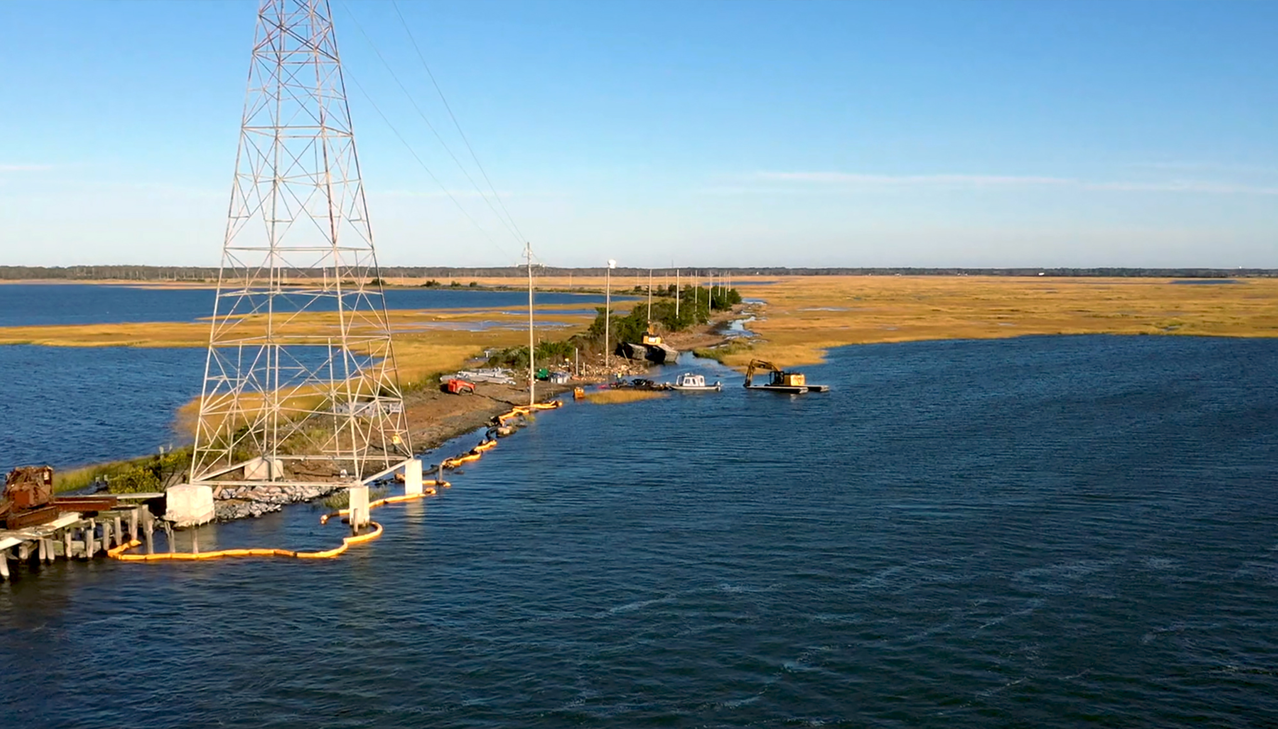
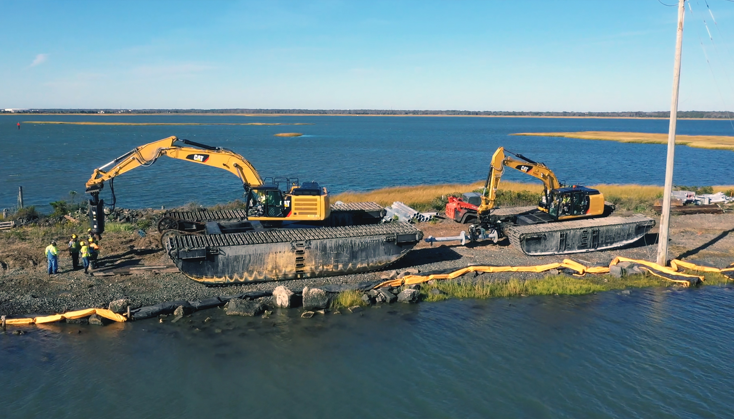
Two additional structures located across the Grassy Sound Channel were not accessible by vehicle and required an innovative approach. Amphibious equipment and workboats were used to access these locations by waterway and install the foundations in a highly sensitive environmental area. The transition from standard access to access by water was a calculated process that required several adjustments. It was important to identify a location next to the water that could serve as a staging yard and launchpad for equipment into the water.
Here, the same excavators used at other structures were transferred onto amphibious tracks that could float in open water and traverse marshy, wetland-type terrain. Workboats pushed the amphibious equipment across the open water to the structure location, where they then could track back onto land. Amphibious sleds were used to transport material in the same manner.
Commitment to Safety
Working on or near water presents an additional set of hazards and controls for worker safety. Measures to ensure safety in this situation included the development and implementation of a project-specific emergency action plan that included detailed waterway training and availability of specialized safety equipment.
Aldridge’s emergency action plan was developed with the assistance of local emergency responders and the U.S. Coast Guard. Key measures taken included closing off the waterway to public boat traffic and the presence of emergency response divers in case of rollover or capsizing. Additionally, the amphibious equipment operators who were in the cab of the equipment during transport over water were required to possess a current scuba certification. Safety equipment included ring buoys, personal flotation devices and Spare Air canisters located inside the cabs of the amphibious equipment.
Maintaining work in compliance with the stringent environmental requirements associated with these sensitive areas also was of utmost importance. A turbidity curtain was installed in the water around the perimeter of the work areas for erosion and sediment control. The sheet piling at the structures located on land also assisted in this, by providing a stable area that did not have continued runoff into the water. Out on the island at the Grassy Sound structures, equipment was refueled and staged overnight in spill-containment areas to prevent oil leaks and other accidental releases from impacting the ecosystem. Finally, an added benefit of using the amphibious equipment was the limited ground pressure it exudes. With that, matting was not required for access or to limit ground disturbances (that is, rutting).
Deep Foundation Design
To facilitate the constructability of the foundations, Aldridge retained Magnum Piering to provide engineering and foundation material manufacturing. Aldridge and Magnum worked together to design the foundations for the site constraints and capabilities of the equipment used in the installation. Two examples of this were limiting the installation equipment based on the size of the excavator that could be placed on the amphibious tracks and using steel to connect the piles to the structure, to avoid transporting concrete across the channel.
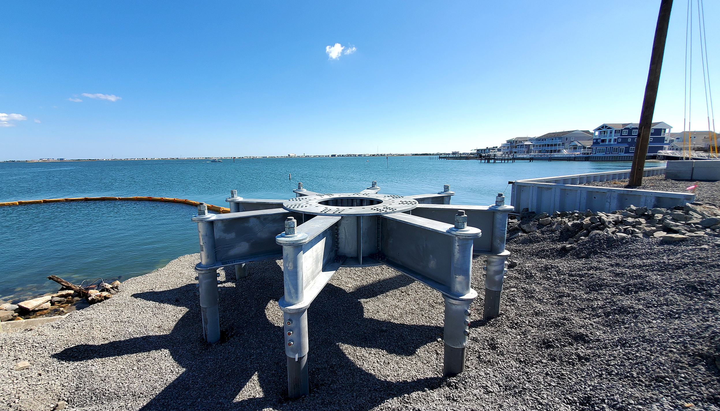
The final engineering design solution used to support the transmission structures consisted of elevated steel grillages on a circular pattern of high-capacity helical piles. Helical piles consist of a central steel shaft with multiple helical bearing elements. The piles are turned into the ground like a large earth screw. They cause minimal disturbance to the surrounding environment and do not produce any drill spoils. The number and size of helical elements are adjusted based on the implied loads and local soil and subsurface conditions. The central steel shaft is sized for combined axial, lateral and overturning loads.
A circular arrangement of closely spaced helical piles was used in the Middle Township to Wildwoods project to support the large monopole structures with higher overturning loads. A radial arrangement of steel beams with a central hub, often referred to as a steel grillage, connected the piles together and provided a bolt pattern for anchoring the structure. Steel grillages eliminated the need for concrete and curing time. Tower structures were set on the grillages immediately after installation.
Helical piles offer many advantages over other foundation types. They can be installed at virtually any depth by adding extensions to the lead section, one after another until the bearing stratum is reached. The length of helical pile sections can be adjusted to accommodate the overhead reach of installation equipment for increased economy or shortened for work under overhead lines, limiting or eliminating power outages during foundation construction. Track-mounted equipment used for helical pile installation is generally lighter and more mobile than traditional pile driving rigs and caissons, reducing mobilization costs and increasing production rates.
A key advantage of helical piles is the installation torque can be correlated to the pile capacity. Measurement of installation torque during helical pile installation serves as an important quality assurance check. The use of torque correlations with capacity is particularly important in areas with limited geotechnical information or changing ground conditions.
Testing and Compliance
On this project, and many deep foundation projects, an ASTM D1143 static load test was conducted to validate the design and confirm pile capacity. A load frame consisting of a main reaction beam and two cross beams was constructed over the first structure location and anchored using four production piles. A sacrificial test pile was installed in the center of the production pile cluster. Load was applied using a standard hydraulic ram. Pile head displacement was measured using dial gauges and an optical transit.
Because of the high confidence in sizing helical piles and the added assurance of installation torque correlations, the load test was conducted in conjunction with production pile installation to reduce mobilization costs and expedite the project. The load test confirmed axial capacity and deflections were close to the predicted pile behavior used as the basis for the design.
All helical pile sections, grillage components and hardware were hot-dip galvanized in compliance with ASTM A123/A153 for corrosion protection. Zinc galvanizing protects the underlying steel in two ways:
It exhibits passivity — a process by which an insulating white film forms over zinc-coated surfaces, significantly reducing electrical conductivity and inhibiting the electrochemical process of corrosion.
It sacrifices itself to protect the underlying steel because of its position on the galvanic series.
To guarantee a long-lasting foundation, engineering calculations were performed to estimate the rate of zinc and steel depletion. All aboveground and belowground foundation components were thickened to account for anticipated corrosion losses during the structure’s design life. Structural calculations also were performed using these reduced sections to ensure adequate factors of safety at the end of the design life.
Grillage and helical pile components were fabricated at Magnum Piering’s manufacturing facility by U.S. workers using U.S. steel following an ISO9001 accredited quality program and shipped to the job site ready to assemble. Pieces were craned together and bolted, and then the entire grillage was craned onto the piles in one unit. Connection bars securing the grillage to the piles were fastened with heavy hex nuts torqued to a specific clamping force. Then a lock nut was tightened over the primary hex nut.
Magnum’s unique design allowed for up to 2.5 inches (63.5 mm) of deviations in pile position in any direction and 2 degrees of pile misalignment, making it straightforward to erect. Before required shipping to the site, Magnum’s quality team assembled the entire grillage to ensure form, fit and functionality. Bolt patterns were carefully coordinated with the transmission tower manufacturer’s drawings.
Mission Accomplished
The Middle Township to Wildwoods project’s success can be attributed to the team’s ingenuity and innovations to combat the unique site characteristics. Without the use of amphibious equipment and a helical foundation solution, this project would not have been possible.
The attention to safety, environmental protection and overall quality made this challenging project stand out. Streamlining design decisions and fully integrating the project team enabled efficient problem solving for the unique set of circumstances.


